Hello to all,
Welcome to the new edition of the SOLIDWORKS Support Monthly News! This monthly news blog is co-authored by members of the SOLIDWORKS Technical Support teams worldwide.
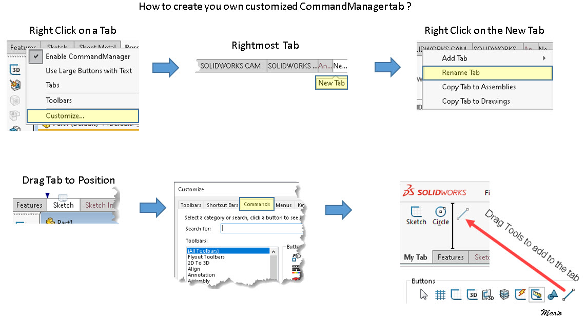
How to customize your own CommandManager Tab?
By Mario Iocco
How to add custom parts to the SOLIDWORKS Toolbox library
By Ayush Agrawal
There could be times, when you might need to add custom components to your Toolbox library. In this blog, I will show you the steps to save custom files in the SOLIDWORKS Toolbox and also some important points that you should consider.
Custom parts do possess some challenges:
- These are not smart components as those which come out of the box in toolbox. Standard hardware parts contains smart information inside the part itself, which means custom parts do not provide much scope of configurability like the standard ones.
- Requires careful collection of correct information/parts from trusted sources.
- This is a onetime task that could take significant time.
Here we will see the steps for saving custom parts in SOLIDWORKS Toolbox Library.
Which parts can be added to the toolbox?
- Parts created inside SOLIDWORKS. It is always good to create parts inside SOLIDWORKS as you can achieve some level of configurability by adding different configurations in the part. Thus you can have different sizes of the hardware saved as configurations.
- Imported neutral format files from another CAD system or downloaded from internet. These are Non-parametric & cannot be editable, so you won’t get much customization. But this saves efforts of part creation process.
(Be careful of what you download from the internet, check of every fastener’s dimensions)
Pre-requisites and Preparations
Before adding a part files to Toolbox, make sure you do some homework:
- If you want some configurations or variation in your custom hardware, then create the configurations in the part file itself.
- If you want to import the files which are in neutral file format (e.g. STEP) then you need to save the part as SOLIDWORKS part format.
For example here, I have created this hex bolt in SOLIDWORKS and then added configurations for variations in the lengths of the bolt. More configurations could also be added clubbing variations in different parameters like Head Height, Shank Length, Thread length, Diameter etc. Use Design Table to optimize the configuration creation process.

You can also create custom properties that you want in BOM or in drawings. For example, here I have added the thread note and part number. You can add multiple different properties as per your need.

Adding Parts to Toolbox
Open the Toolbox Configuration tool, found under Tools > Options > System Options tab > Hole Wizard/Toolbox. Select the ‘Configure’ button. The tab “2 – Customize Hardware” defines available Toolbox standards library.

Now in the Toolbox Configuration window, right-click on a folder where the new item needs to be saved under and select “New Folder” or “Add File” to add a file in that folder. Then locate the required part from the popped-up open window and add to the list. Keep adding files are needed.
The new folder could also be completely separate from existing standards. In that case, right-click must be done on the Toolbox Standards folder name. One may decide to create sub-folders under the newly created folder.
In the following image, ANSI Inch > Hex Head folder is selected and we will add a new hex bolt type.


By clicking on each individual new item, General settings such as file name, description and other custom properties of the part can be modified.
Make sure you save the Toolbox changes.

Now this part can be added to an assembly in the same manner as the other toolbox items.

Also refer this help document for more information:
http://help.solidworks.com/2021/english/SolidWorks/toolbox/t_tbx_standards_custom.htm
Implementing License timeout minutes using Administrative Profile in DraftSight®
ByNav Mahajan
Since the license timeout settings for DraftSight® cannot be controlled using Options file in DraftSight, we can use Administrative profile to override license timeout settings in DraftSight.
A CAD administrator can enforce the License Timeout specification by using a profile XML file. The DraftSight® Help defines profiles as follows:
“Individual profiles store configuration settings for the application environment that are not saved with drawings. Administrative profiles let workgroups and companies to share common configurations and configuration overrides.”
Individual profiles are user settings, whereas administrative profiles are administrator-enforced settings.
To enforce the License Timeout specification using Administrative Profile, you will need to create a new .xml file only with setting that we want to override. It will look as below example:
<?xml version=”1.0″ encoding=”windows-1252″?>
<settings>
<group name=”current workspace”>
<setting type=”QString” name=”workspace name” value=”Drafting and Annotation”/>
</group>
‘<group name=”preferences_license”>
<setting value=”true” name=”licensetimeoutenabled” type=”bool”/>
<setting value=”30″ name=”licensetimeouttimeinminutes” type=”int”/>
</group>’
</settings>
Once done, save this file as ‘administrative_profile.xml’ and put it on a location which is accessible to all the users or a workgroup.
Now, create a profile override xml file. A file named ‘profile_overrides.xml’ provides the locations of administrative profiles to use and determines for what versions of the software they are used.
To become operative, the file has to be placed on local computers into a specific application related folder:
‘C:\ProgramData\Dassault Systemes\DraftSight’
The XML file uses a specific syntax as shown in the following example:
<?xml version=”1.0″?>
-<profileoverrides>
-<version build=”*”>
<setting value=”[Location where Administrative Profile is placed]”
type=”QString”/>
</version>
</profileoverrides>
Noteworthy Solutions from the SOLIDWORKS Knowledge Base
In SOLIDWORKS® software, how could I solve issues due to Equations and Potential Circular Reference?
With added changes in Equations with last SOLIDWORKS® versions, it happens often that opening legacy files (earlier than SW 2021), in Equations, the ‘Automatic solve order’ is disabled, and in the ‘Name’ column, alert yellow icons are shown. To get more information, see Solution ID: S-079511
Why does my IFC format import file display different colors than the SOLIDWORKS® IFC format export file?
To retain the colors when importing a model to IFC readers, you must use the SOLIDWORKS® IFC4 file format and activate the ‘Tessellation’ option.
To get more information, see solution ID: S-079517
How do I troubleshoot the following error that appears in the log file of the SOLIDWORKS® PDM ‘Convert’ task?
‘Failed to run SOLIDWORKS macro.’
The SOLIDWORKS® PDM ‘Convert’ task depends on the SOLIDWORKS CAD software. When the task runs, it evaluates the task script and generates a SOLIDWORKS macro. The task starts SOLIDWORKS, passes this macro for processing and waits for SOLIDWORKS to respond. To get more information, see Solution ID: S-079527
In the SOLIDWORKS® Plastics application, why is the ‘Number of Elements’ option no longer available in the ‘Runner System’ PropertyManager?
Effective with the release of SOLIDWORKS® Plastics 2022, the software automatically calculates the ‘Number of Elements’. To get more information, see Solution ID: S-079524
That’s it for this month. Thanks for reading this edition of SOLIDWORKS Support News.
Originally posted in the SOLIDWORKS Tech Blog.