Beginning with this release, Product Document Creator has been functionally transformed into Manufacturing Definition Creator, which combines the benefits of model-based definition software with the traditional look and feel of 2D drawings. Manufacturing Definition Creator is the new single source of truth for dimensions, tolerances, and annotations that exist in 2D and 3D with the ultimate output flexibility of model-based practices or 2D drawings.
The February 3DEXPERIENCE® Works release of browser-based design and engineering capabilities is now available. The power and flexibility of these applications on the platform is significant and can become an essential part of your product development strategy. Let’s take a closer look at the enhancements. You can check out the FD01 2022 video here.
Assemble Smarter
With the power of machine learning, this update revolutionizes the way you put together assemblies, which become as intuitive as that well-known brand of construction blocks, but with any shaped geometry. The Design Assistant now has a mode that can automatically invoke a component when dropped close to something similarly shaped. It can apply up to three appropriate mates. Check out the video below.
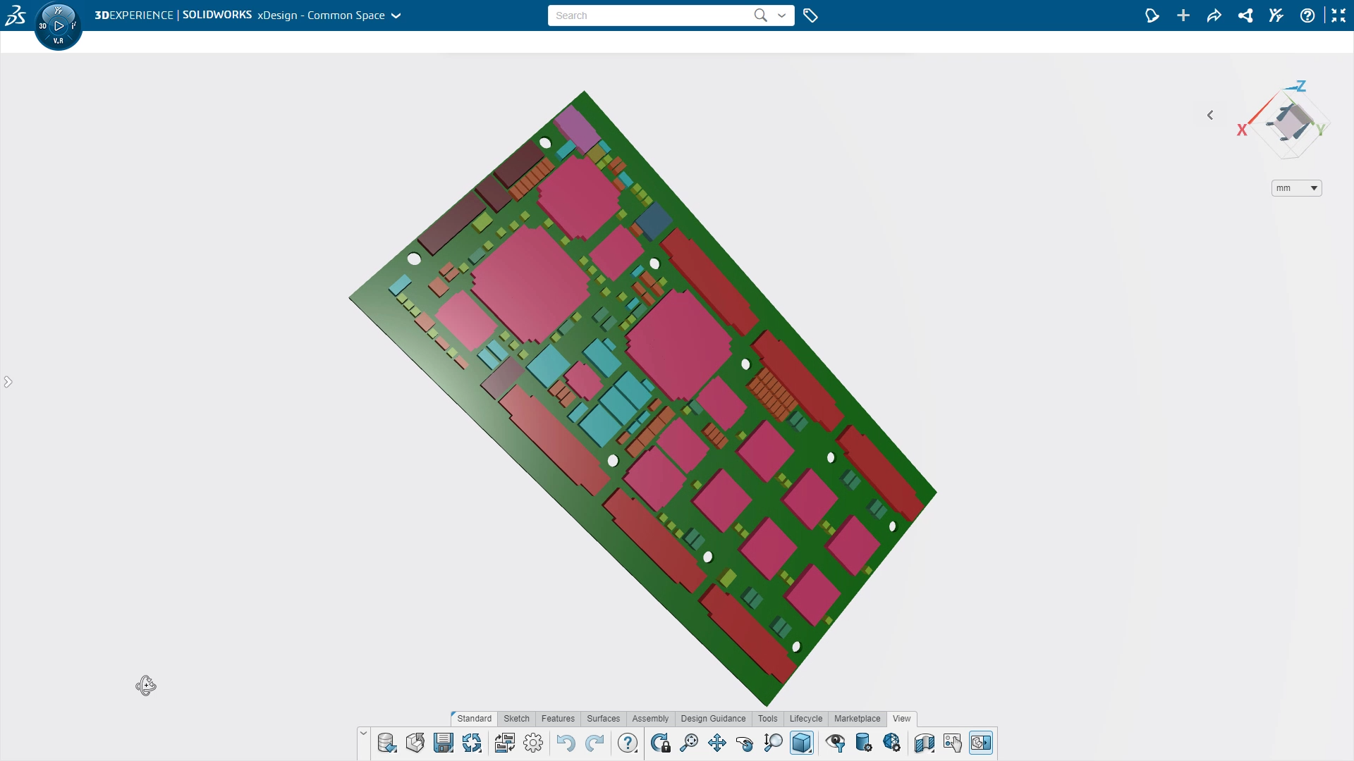
Import ECAD Files [New!]
The number of products that contain printed circuit boards (PCBs) continues to grow exponentially. Now you can import IDF files, which are typically 2D designs, directly from your ECAD software. The application converts files to 3D representations of the PCB that can be used to design extremely accurate enclosures. Working in parallel with PCB designers to ensure mechanical designs properly integrate with your electronics saves time, reduces manufacturing issues, and improves design performance.
Smoother Design Workflows [New!]
If you forget to create a reference sketch, hole, or other feature while in a command that requires one, you can pause the command and create your sketch before automatically returning to the previous command—all without losing your place. Fewer interruptions to your workflow enable faster, more productive design.
User Parameters
You can now set up overarching custom parameters that drive an entire part or assembly as named parameters. So rather than looking for the right dimension and changing many parameters separately, you can drive everything from the Design Manager and change the dimensions as a group. All the dimensions and equations can reference these parameters in the design tree. Make significant changes more quickly and speed efficiencies with personalized parameters.
Reduce Design Rework Time
If another designer has changed the file you are working on, it will be graphically flagged as out of date in the Design Manager. This flag makes it easier and quicker to tell when items are outdated, so you can update the items and reduce time spent on rework.
Import Revit Files for AEC Applications
Mechanical, electrical, and civil engineering disciplines are being called on to work more closely together. Now you can work concurrently with architects and building designers to ensure your designs properly integrate with theirs, which increases efficiency and reduces manufacturing issues.
Keyboard Shortcuts on Tool Tips
Keyboard shortcuts were previously listed only in the Help file, but now they are also in the Tool Tips. Hovering over commands on the Action Bar displays a long description of the command as well as a keyboard shortcut in parentheses. This makes it easier to learn keyboard shortcuts for greater efficiency.
New User Assistance Panel
The design and layout of the User Assistance panel is now consistent across all dashboard apps on the 3DEXPERIENCE platform; the User Assistance panel is also dynamic based on what is selected within the apps. For example, when you use the Line Tool, User Assistance automatically brings up the help section for the Line Tool. The consistent look and feel of the User Assistance panel improves usability.

Intelligent Tangency for Parting Lines
When you manually select portions of a parting line using the tangency accelerator, the tangent line is now automatically trimmed at the break in the parting line. This saves time and effort when customization is required of an existing partial parting line.

Design Assistant for Manual Parting Lines
If you don’t have a Parting Line at all or you want to create one manually, check out the new Design Assistant for Selection that allows you to toggle through multiple suggestions to connect from one side of a part to the other. Save time when manually creating Parting Lines and get the Parting Line you want faster than picking individual segments.

Thickness Analysis Check
For plastic parts you typically want a consistent thickness of material, because a plastic part that is too thick will shrink and create a divot as the part cools down during manufacturing. The new Thickness Check tool lets you perform two methods of analysis to prevent these kinds of issues: 1) the rolling ball method, called Sphere, or 2) normal distance between faces check, called Ray.
Prevent sink marks, evaluate structural design integrity, and validate a part’s capacity to fill properly with this new tool. Also, you can manually check thicknesses at specific locations by clicking on an area. Color coding enables you to easily see areas of the model that are too thick or thin.

Hopper Feature (with Bends)
The Hopper feature has new options to control the type of bends within the lofted transitions, making it quicker and easier to design accurate, manufacturable, lofted sheet metal geometry. Full-bend transition parameter controls eliminate manual edits, increasing your efficiency.

Additional Bend Options
Before this release, the only Bend Allowance option was the K-factor equation. Now Bend Allowance and Bend Deduction, new sheet metal parameter options, calculate flat pattern length. Build realistic sheet metal designs that account for stretching and deformation during the manufacturing process. These new parameters also help you build flat patterns that accurately reflect your internal manufacturing standards.
DXF Support for Modified Flat Patterns
The DXF export update includes changes to the flat pattern. The included changes are not reversed back to 3D or folded geometry; the changes are only reflected on a flat pattern—changes won’t disrupt your folded model. Seamlessly capture manufacturing intent and maintain folded geometry integrity by making reliefs and cuts only at the flattened level.
2D Drawing to 3D Model Connection
Create 2D drawings based on a 3D view for a flexible solution that outputs both a model-based definition (MBD) and 2D drawings with no rework required on dimensions and annotations. You can create and publish 2D drawings with drawing views, sheet formats, notes, tables, multi-sheets, view scaling, automatic geometry updates, and save as a PDF. Now you can create 2D presentations for manufacturing definitions with seamless connection to 3D geometry and annotations and build 2D drawings for downstream consumption that are always up to date with the model.

Easily Place Gussets, End Caps, and Plates
The new workflow in this release is similar to that of SOLIDWORKS desktop. When placing a gusset between two structural members, select the two faces where you want to place them. Similarly, you can specify the dialogue for the dimensions of that gusset or plate: Either select the end face of the member to define placement or select the entire member. Enjoy the time savings of defining placement for gussets, end caps, and plates.

Simplify Pierce Point Selection for Structure Members
Selecting member pierce points graphically is faster and more efficient. Depending on the previous view, it was difficult to tell which structure member was the upper right or lower bottom, for example. This enhancement simplifies the process because you don’t need to know the name of the pierce point, just click on it in the graphics area. You can also specify a custom pierce point.

Faster Selection of Geometry
Power users will appreciate this shift selection improvement, which selects the shortest distance between two selection points. Enjoy faster selection of geometry across a subdivision body. Use shift select to select faces in a row regardless of whether those faces are in a face loop.

Net Surface Primitive
You can now create your own primitives using a loft, a boundary condition, or a sweep. Start by defining a surface using familiar parametric commands. Then use freeform subdivision (Sub-D) modeling to modify the shape of your customized primitive. Also, you can toggle between the customized parametric surface or subdivision surface. To increase design efficiency, choose pre-defined primitives or create your own with the Net Surface command.
Always Connected
With product development teams geographically spread out now more than ever, companies need additional tools to bring products to market quicker and more efficiently. The platform makes it easy to work with people inside and outside your company, including customers, suppliers, and manufacturers. You can simplify your communication workflow and improve productivity because everyone works from the same platform. And because data management is built in, you have design data and communication audit trails all in one easy-to-access location.
Check out the video below.
Originally posted in the SOLIDWORKS Blog.