Applying Mate References to your commonly used parts and assemblies is a great way to automatically mate them together quickly and easily. Mate References allow you to simply drag a part or sub-assembly into an assembly and have it mated automatically. Think of a pulley mated to a shaft automatically with the correct orientation. You can add one, two, or three mate references using Concentric, Coincident, Parallel, and Tangent mates.
Some considerations must be made on how you want to use Mate References. First you’ll need to determine whether or not to name the Mate Reference. Naming the Mate Reference will aid in automatically mating two parts together by dragging and dropping them in a top level assembly. The same name of the Mate Reference should reside in both parts being mated. If the Mate Reference isn’t named, and the Default name is retained, the mate reference can still be used to when adding the part to an assembly. Typically, using the Default name will restrict the number of mates created by the mate reference to one, but there is a way to get two mates applied by using the “peg in hole” technique.
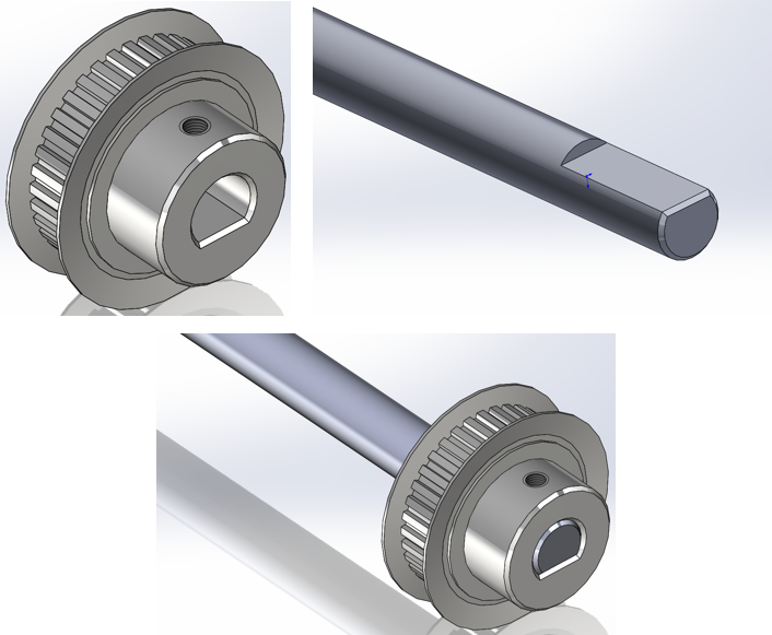
Let’s take a look at how the “peg and hole” technique works. In this example we’ll use a pulley with a “D” bore and set screw tapped hole. The pulley must be orientated correctly so the hub is positioned towards the end of the shaft.
You can find Mate References from the Insert Pulldown Menu under Reference Geometry.

Here’s the Property Manager for Mate Reference. For this example the Reference Name will remain “Default”.

The Primary Reference will be the edge of the “D” bore. The Mate Reference Type will be Default and the Mate Reference Alignment will be Any. Using the Edge of the “D” Bore signals SOLIDWORKS to apply two mates in the assembly; a concentric to the shaft OD and a coincident to the end face of the shaft. One thing to keep in mind is the coincident mate will be placed as anti-aligned and can be switched to aligned by using the Tab key. The mate will flip and flip the pulley to the correct orientation.

To describe aligned and anti-aligned mates we’ll use these two parts and mate the bottom faces using a coincident mate. By default the Aligned option is applied to the mate. This means the arrow pointing out of the highlighted faces on the both parts is oriented in the same direction.

By selecting the anti-aligned option the part flips and the arrows for each face are now pointing in opposite directions.

Here’s a video showing how Mate References work when the Pulley is dragged and dropped in the Shaft-Pulley Assembly. This is the behavior without a named Mate Reference. The important thing to remember: Use the TAB key to flip the mate alignment.

Now, let’s set-up the same parts using a named Mate Reference. The Reference Name is Pulley and will use 3 mates to fully position the pulley onto the shaft when the pulley is added to the assembly. The Tertiary Reference Mate alignment needs to be changed to Aligned since we want the Pulley to be assembled on the shaft and not mated to the end of it if the alignment was Anti-Aligned.

The Shaft will be set-up the same way.

Here’s a video showing how the Named Mate Reference simplifies the process of mating two parts together in an assembly.
Now that you know how to apply and use Mate References you will be able to save a lot of time by not having to repeatedly mate commonly used components together.
Originally posted in the SOLIDWORKS Tech Blog.