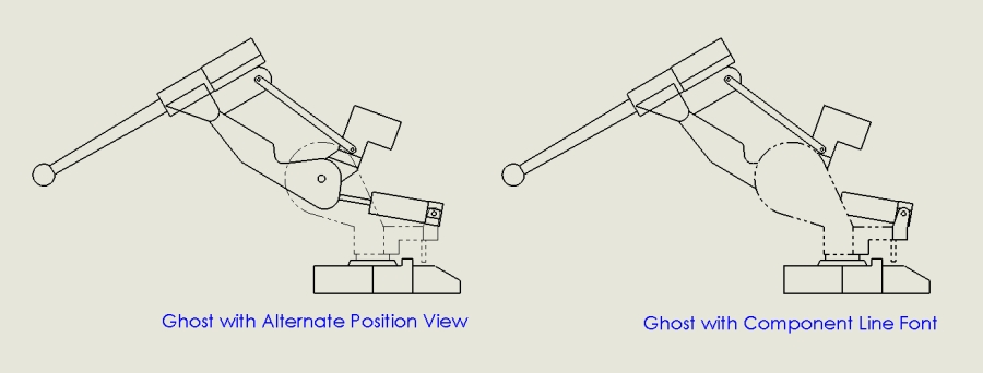
SolidWorks has many great drawing creation productivity tools, one of which is Alternate Position Views. This tool allows you to depict in a drawing the range of motion of an assembly component by showing it in different positions.
Another great use for this is to show a component in a drawing view as a phantom or ghost. Why use Alternate Position View to achieve this instead of changing the Component Line Font of the part in the drawing view? Well, the main difference between the two techniques is that Alternate Position Views are “transparent”, that is, only edges of the part are shown in the drawing but the faces are not. The image below shows the difference:
So how do you use Alternate Position Views to depict range of motion of an assembly component, or depict a “ghost” part in an assembly? In brief:
- Select a view and start the Alternate Position View command.
- Create a new configuration, or select an existing one.
- The Alternate Position View is exactly overlaid on the original view.
- Manipulate the original view to hide part to be classed as a ghost.
- The Alternate Position View part will now show through (as per step 3).
That’s it! Have look at the movie below for full workflow details.
More tips next time from the SolidApps team.

