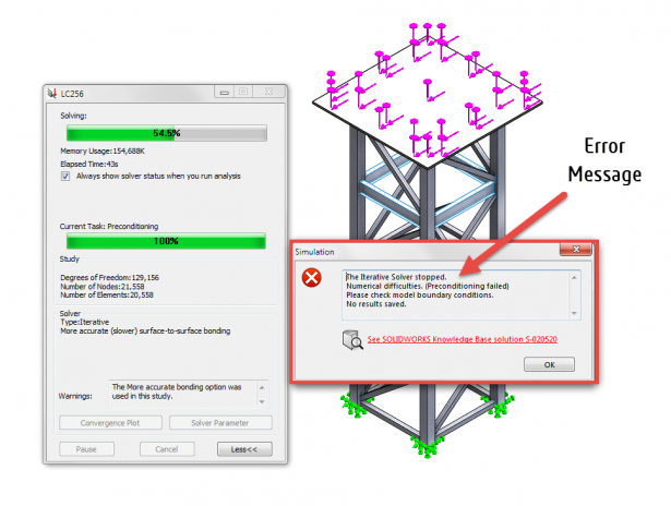
You have probably had a situation in the past where the SOLIDWORKS Simulation solver has given an error message as shown below, about a model having insufficiently restrained degrees of freedom or having to check the model boundary conditions.
SOLIDWORKS Simulation has a built in tool called “Find Unconstrained Bodies” found in the feature tree under Contacts, Find Unconstrained Bodies. See image below.

In the property manager dialog box, simply click on the “Calculate” button as shown below. This performs a simplified analysis (called as degree of freedom analysis or D.O.F) to identify which bodies are not fully restrained and provides feedback on the specific degrees of freedom.

As you can see, there are a lot of bodies in this model that are completely free to move! The reason for that is there are weld gaps between parts to account for tolerances as shown below. Simulation does not understand this functional intent and so this needs to be conveyed using the appropriate boundary conditions!

Often times, contact conditions are used to describe the physical interactions between parts of an assembly or between bodies of a multi body part. While Simulation provides an easy to use and intuitive option to define contact conditions, it is easy to miss one of these in a larger or complex model where several components might come into contact during deformation. And if the contacts are the only means to prevent bodies from any rigid body motions, these would show up in the solver aborting abruptly during the solve.
In the video below, a brake caliper example is used to illustrate how the Show Contact tool can help troubleshoot issues with contact definitions.
Now behind the scenes, the solver uses constraint equations to connect the specified geometry in the contact definition. This is visually mapped and shown as well if you select the check box “Include solver generated contacts”. Note that you will have to mesh the model first before you can check this option. Or else its grayed out!The contact detection above is based upon geometry used in the contact definitions. And is great for ensuring all contact definitions are in place for simulation.
The question you may have us Why is this important? By being able to visualize the contact area used by the solver, immediate feedback is provided on the coarseness of the mesh in the contact areas. It is an ideal indicator of whether mesh refinement is needed in contact areas or not to get better resolution of the contact area by the solver and hence accurate results! An example if shown below to illustrate the differences between the geometry based and solver based contacts

Originally posted in the SOLIDWORKS Tech Blog.