One of the great benefits of SOLIDWORKS is the way you can capture work and re-use it many times over. There’s no better way of capturing work then by creating and using Smart Components. You’re probably asking yourself what’s a Smart Component? Is it something new recently added to SOLIDWORKS? Nope. Smart components have been around a long time and are probably underutilized especially when using off the shelf components which require additional features in order to complete their definition. Think of a bearing pressed on a shaft. The shaft has to have a specific diameter and tolerance in order to press the bearing onto the shaft. Every time you use that bearing in an assembly you would have to look up the press fit requirements in the manufacturers catalog and apply that to the shaft for each bearing and shaft combination. Lots of extra work is involved plus the chance for error goes up because of the manual effort involved. Wouldn’t it be nice if the bearing was “smart” enough to have the press fit information already baked into it? Smart Components do exactly that.
This blog will show you step-by-step how to create a Smart Component. In this example we’ll use a flanged bronze bushing like this:
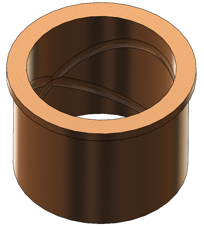
From the bushing manufacturers catalog the fit for the housing bore is H7 which is +0.03/-0mm. The housing fit tolerance is very important to the life of the bushing. If it’s not correct premature failure will occur.
STEP 1
Create a small block bigger than the bushing you will use. In this example the block is 100x100x60mm. The block will be used as a “dummy” component which will define the bore and additional features like chamfers and fillets for the bushings bore.

STEP 2
Create an assembly from the block. Next insert the flanged bushing and mate it to the top face of the block using a coincident mate. It’s not important the bushing is centered in the block.

STEP 3
Create the bore, chamfer and fillet for the bushing. The bore nominal diameter is 70mm with an H7 fit. The depth of the bore is 50mm. A 1.5mmx45° chamfer is applied to the bore top edge and a 1mm max fillet is applied to the bottom inside corner of the bore.
It’s important to understand how these features need to be created in order for them to work properly. The external references for the bore, chamfer and fillet have to be associated to the bushing and not the block. The bore will be a child of the underside face of the flange. The chamfer and fillet will be children of the bore.
Edit the block in context of the assembly. The sketch plane for the bore is the underside face of the flange.

Sketch a circle 70mm in diameter and apply a Fit with Tolerance, H7.

Cut extrude the circle 50mm deep.

Next apply the 1mm fillet to the bottom inside edge of the bore. This is important to apply the fillet first before the chamfer. Next create the chamfer on the top edge of the bore. Select the face of the bore and not the top edge. This keeps the reference of the chamfer associated to the bushing and not the block. If you created the chamfer before the fillet you would get 2 chamfers on the top and bottom of the bore. Then you wouldn’t be able to apply the fillet in that case.

STEP 4
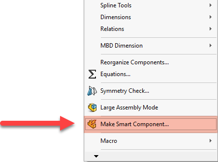
This is where the magic happens. Under the Tools pull down menu select Make Component Smart.
In the Smart Component Property Manager make the following selections:
- Smart Component = Flanged Bronze Bushing
- Components = There are no other components associated with this Smart Component.
- Features = bore, chamfer and fillet are selected from the block.
- Select OK to complete the Smart Component.

STEP 5
So what happened? A couple of things. First, a Smart Feature folder was added in the design tree of the bushing. Opening it up reveals the Features and References folders. In the Features folder the bore, chamfer and fillet are listed. In the References Folder the “Component for feature” is listed and under that the cut-extrude for the bore is listed.

The other thing that happened is the bushing component icon has a lightning bolt to signify it’s a Smart Component.

STEP 6
When using OTS components it’s best to put them in the Design Library and share them with the rest of the engineers in your organization. If you’re using PDM Professional and have the Design Library in the Vault then an administrator has to add the Smart Component to the Design Library.
How to use a Smart Component
Once the Smart Component is added to the Design Library you can drag and drop into an assembly and apply the Smart Features contained in the Smart Component to the mating component. Here’s a short video showing how to do this:
Additional automation can be added to the bushing by defining Mate References so the bushing snaps into place when dragging it from the Design Library into your assembly.

Originally posted in the SOLIDWORKS Tech Blog.