Before starting with the main issue of the article, let’s review how the sheet metal thickness works when dealing with multi body parts.
When you create a sheet metal part, you have one Sheet-Metal feature (Part Thickness) and as many Sheet-Metal# (Body Thickness) features as sheet metal bodies. The “Thickness Global Variable” always reflects the part thickness. (Fig. 1)
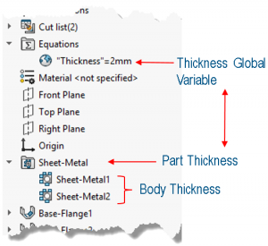
Fig. 1
By default, when creating a sheet metal body, the thickness of the body is controlled by the part thickness. If you want a body to have a different thickness from the part thickness, you edit the Sheet-Metal# body feature, check the “Override default parameters” and enter the desired thickness (Fig. 2)

Fig. 2
In this particular example, the part thickness still is 2 mm, and it will only control the thickness of the U-shaped body (Fig. 3)

Fig. 3
Any additional bodies created in the part will — by default — have the part thickness (2 mm) (Fig. 4)

Fig. 4
Now you insert a mirror part, with the “sheet metal information” option checked and still linked to the parent part (Fig. 5)

Fig. 5
Editing the mirrored part sheet metal feature shows the part thickness was “transferred” to the mirrored part thickness. Also, the thickness global variable is still representing the part thickness of the mirrored part. (Fig. 6a)
Editing the sheet metal features of the bodies show that now each body has the “override default parameter” checked. (Fig 6b and 6c).This means that the thickness of these two mirrored bodies are not controlled by the mirrored part thickness. The reason for checking the “override default parameter” is that otherwise, all the bodies would respond only to the mirrored sheet metal part thickness and have a 2 mm thickness.
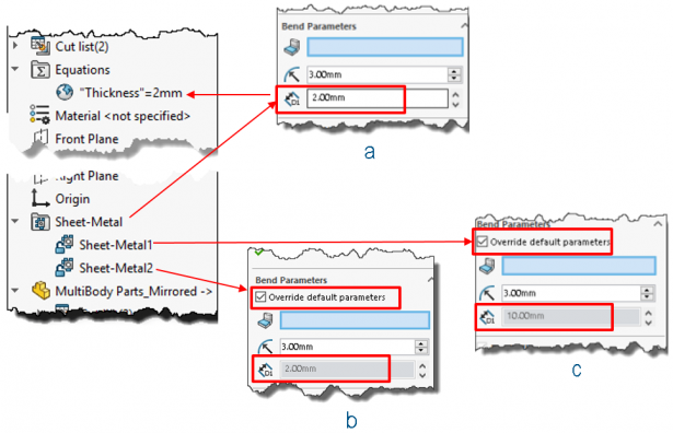
Fig. 6
At this point you add another body to the mirrored part. Notice the “Override default parameter” is unchecked. Therefore, the new body will have the mirrored sheet metal part thickness at 2 mm (Fig. 7)
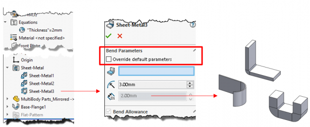
Fig. 7
Now you change the parent/seed sheet metal part thickness. Notice the mirrored part thickness and global thickness variable does not change. (Fig. 8)

Fig. 8
However, the U-shaped body –which was linked to the original/seed part — will update (Fig. 9). This was the same body that was responding to the seed part thickness (see Fig. 3)

Fig. 9
Why does the mirrored part thickness/global variable not change? Is this correct?
Yes, that is correct. Although we call the derived part a “Mirror Part”, in reality this is a different part. Even though the U-Shaped body has the “Override default parameters” option checked, this is the only body linked to the seed part thickness.
In summary: (Fig. 10)
- The thickness global variable always displays the part thickness value.
- When creating a mirror part, all the bodies in the mirrored part have their “Overall default parameters” options checked.
- The part thickness of the seed and mirror part are independent from each other.
- The mirror part could have bodies which may or may not respond to the seed part thickness.
- Only the body in the mirror part — which responded to the part thickness in the seed part — will be linked to the seed part thickness. All other bodies will respond to either to the new part (mirrored part thickness) or to their individual body thickness.

Fig. 10
Originally posted in the SOLIDWORKS Tech Blog.