Sheet metal parts can have sketches in the Folded and the Flat Pattern states (Fig. 1) Sketches created in the folded state can have an equivalent “transformed” sketch in the Flat Pattern state.

All sheet metal parts have a fixed face. The fixed face is the one that remains in the same position when unsuppressing the Flat Pattern. (Fig. 2)

Sketches created in fixed faces will not be transformed. The sketches created in non-fixed faces will be transformed when viewed in the Flat Pattern. (Fig. 3)

The circular sketch was created in the Flat Pattern fixed face, it does not need to be transformed. The square sketch was not created on a fixed face, it was transformed when unsuppressing the Flat Pattern feature (Fig. 4)

The transformed sketches will be visible in the Flat Pattern feature, under the “Sketch Transformation” folder. The sketches that has been transformed will be hidden in the Folded state (Fig. 5.)

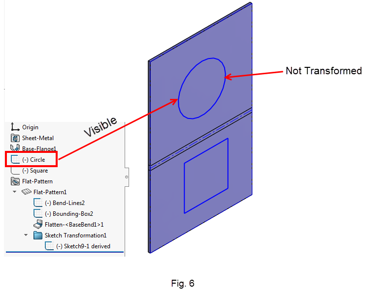
The non-transformed sketches will remain visible in the Folded state (Fig. 6.)
The transformed folder does not exist when the Flat Pattern is suppressed (Fig. 7.)

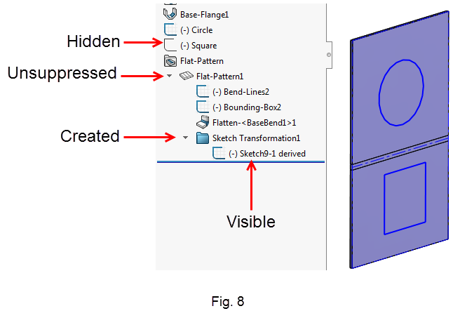
The transformed folder is created only when unsuppressing the Flat Pattern feature (Fig. 8.)
Sketches in the Flat Pattern Drawing View
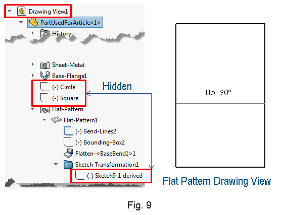
When you create a Flat Pattern drawing view, the system creates a flatten derived configuration. After the creation, the sketches in the flatten derived configuration and drawing become independent from each other. That is, if you want to see the transformed sketches being displayed in the Flat Pattern drawing view, you must expand the drawing view Feature Tree and manually show those sketches (Fig. 9)
Originally posted in the SOLIDWORKS Tech Blog.