Hello to all,
Welcome to this new edition of the SOLIDWORKS Support Monthly News, coauthored by members of the SOLIDWORKS Technical Support teams worldwide.
It’s SOLIDWORKS Knowledge Base Month!
OK, that’s not really true: Every month is SOLIDWORKS Knowledge Base Month! Do you count yourself among the thousands of SOLIDWORKS professionals who search the Knowledge Base (KB) each month to find answers to questions and solutions to problems? There is a good chance that there is a solution already available that will answer your support question. If so, a KB Search can save you valuable time.
Key indicators:
- More than 30,000 Solutions published to users
- Solution with most views has more than 34,000 of them
- 4,500 Solutions reviewed and updated in the last 12 months
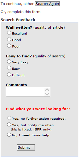
As you can imagine, much activity takes place to ensure we are delivering useful and actionable information in the Knowledge Base, and our KB users play an important role in helping us define and deliver high value KB content. As an example, we actively review the information you submit in the Submit Feedback form on the KB Search web page (see the screen capture to the left); we use your feedback to identify areas of need and topics that we can improve and refresh. If you are unhappy with a Solution, please give us a hint in the Comments field about the nature of your dissatisfaction (Solution may be obsolete, duplicate or incomplete for instance).
There’s nothing so obvious that a short comment won’t help clarify.
SOLIDWORKS 2018 Beta – looking back 10 years ago
While we eagerly wait for the beginning of this year’s Beta program (around the end of June) to discover and test all the new features in version 2018, let’s take a look back at what shook the world of SOLIDWORKS ten years ago, in version 2008. It is really amusing to see how what we now take for granted once made the big headlines in the What’s New pages of the documentation!
SOLIDWORKS
- Instant3d! – you can now grab any face or feature and graphically drag to resize the geometry! Turn cuts into extrudes and vice versa!

- Fun fact! When version 2008 was released, it shipped in bigger boxes than version 2007: two DVDs (for the x32 and the x64 editions) were included, whereas in version 2007 both editions could fit on a single DVD.
- S Key shortcut menu – the S key launches a context sensitive toolbar next to the cursor – this is huge time-saver when modeling.

- RealView. Check out these scenes!

- Let’s not forget the UI overhaul, now with a CommandManager…

- … and an expandable menu bar

-
New tools:
-
DimXpert for parts is a set of tools that applies dimensions and tolerances to parts according to the requirements of the ASME Y14.41-2003 standard.
-
TolAnalyst is a tolerance analysis application that determines the effects that dimensions and tolerances have on parts and assemblies
-
DFMXpress checks your designs for manufacturability.You can identify areas that are difficult, expensive, or impossible to machine early in the design process.
-
DriveWorksXpress is a design automation tool you can use to automatically generate parts, assemblies, and drawings based on predefined design information.
-
SOLIDWORKS Simulation
- New study types
- Pressure Vessel
- Linear Dynamic: Modal time History, Random Vibrations, Harmonic
- Nonlinear Dynamic
- You can mix beams, shells, and solids in a mixed mesh study
SOLIDWORKS Motion
-
Motion Studies now use the MotionManager (adapted from SOLIDWORKS Animator).
SOLIDWORKS Flow Simulation
- Project is saved to model. Now the created project is saved together with the model’s geometry in the same CAD file, eliminating the need to have the separate project file. You do not need to worry about the project file (the .fwp file) anymore when copying or moving the model files.
-
New types of fans. The Axial and Radial fans
-
Automatic correction of invalid contacts and Highlighting of invalid contacts remaining in the model.
-
Real gases
If you liked that time travel session, check out the May 2014, June 2014 and May 2015 editions of the SOLIDWORKS Support Monthly News for a reminder of the best enhancements in versions 2004, 2005 and 2001 respectively.
Understanding sheet metal sketches, transformed sketches and how they behave
By Mario Iocco
Sheet metal parts can have sketches in the folded and in the flat pattern state (Fig. 1)

Sketches created in the folded state can have an equivalent “transformed” sketch in the flat pattern state.
All sheet metal parts have a fixed face. The fixed face is the one that remains in the same position when unsuppressing the flat pattern. (Fig. 2)

Sketches created in fixed faces will not be transformed. The sketches created in non-fixed faces will be transformed when viewed in the flat pattern. (Fig. 3)

The circular sketch was created in the flat pattern fixed face., it does not need to be transformed. The square sketch was not created on a fixed face, it was transformed when unsuppressing the flat pattern feature (Fig. 4)

The transformed sketches will be visible in the flat pattern feature, under the “Sketch Transformation” folder. The sketches that has been transformed will be hidden in the folded state (Fig. 5.)

The non-transformed sketches will remain visible in the folded state (Fig. 6.)

The transformed folder does not exist when the flat pattern is suppressed (Fig. 7.)

The transformed folder is created only when unsuppressing the flat pattern feature (Fig. 8.)

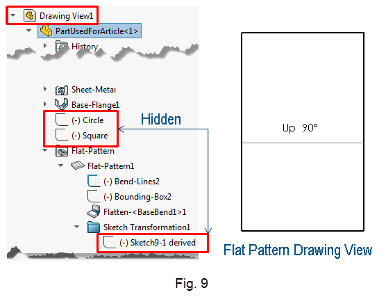
Sketches in the Flat Pattern Drawing View
When you create a flat pattern drawing view, the system creates a flatten derived configuration. After the creation of the flat pattern drawing view, the sketches in the flatten derived configuration and drawing become independent from each other. That is, if you want to see the transformed sketches being displayed in the flat pattern drawing view, you must expand the drawing view feature tree and manually show those sketches (Fig. 9)
Simulation Step-Up Series
Last month, Omar discussed the topic of Basic failure analysis. This month, Reza discusses the topic of Accuracy and Convergence.
Next month, Ramesh will come back and discuss the topic of Viewing results (Parts 1 & 2).
Noteworthy Solutions from the SOLIDWORKS Knowledge Base
![]() After installing SOLIDWORKS® 2017, why does the ‘Pack and Go’ feature not preserve the full folder path?
After installing SOLIDWORKS® 2017, why does the ‘Pack and Go’ feature not preserve the full folder path?
‘Pack and Go’ now uses short, relative folder paths.
In versions prior to SOLIDWORKS® 2017, the entire path was used, causing problems with the Windows® 256 character limit.
For more information about this, see this What’s New topic.
In response to customer feedback, SOLIDWORKS Development now offers a solution to restore the previous functionality with a modification to the registry keys.
For more detailed information, see Solution Id: S-073053.
![]() Using SOLIDWORKS® Enterprise PDM 2015 or later versions, how do I manually install the 64-bit version of the Autodesk® AutoCAD® add-in?
Using SOLIDWORKS® Enterprise PDM 2015 or later versions, how do I manually install the 64-bit version of the Autodesk® AutoCAD® add-in?
When you install the SOLIDWORKS® Enterprise PDM CAD Editor client on a system that has a 64-bit version of the Autodesk® AutoCAD® software installed, you can select to install the AutoCAD add-in. If SOLIDWORKS PDM client installer does not detect the AutoCAD software, or if you install AutoCAD after finishing the SOLIDWORKS PDM client installation, you can install the add-in manually.
For more detailed information, see Solution Id: S-072975.
![]() How do I manually calculate the ‘Acoustic Power’ and ‘Acoustic Power Level’ to validate the values given by SOLIDWORKS® Flow Simulation?
How do I manually calculate the ‘Acoustic Power’ and ‘Acoustic Power Level’ to validate the values given by SOLIDWORKS® Flow Simulation?
The foundation to such a hand calculation is to follow the explanation and equations given in the “Noise Prediction” topic of the Online Help.
Attachments to Solution Id: S-072876 provide:
• A sample calculator in an Excel spreadsheet
• A sample part model
• A screen capture of ‘Acoustic Power’ and ‘Acoustic Power Level’ results
![]() Is there a limit to the number of ‘Injection Locations’ I can place on a SOLIDWORKS® Plastics mesh?
Is there a limit to the number of ‘Injection Locations’ I can place on a SOLIDWORKS® Plastics mesh?
The limit to the number of ‘Injection Locations’ you can place on a SOLIDWORKS® Plastics mesh is equal to the number of nodes comprising your mesh.
For more detailed information, see Solution Id: S-072792.
![]() In the SOLIDWORKS® Simulation software, why do I receive the error ‘Cyclic symmetry is not supported by Frequency [or Buckling] Analysis…’?
In the SOLIDWORKS® Simulation software, why do I receive the error ‘Cyclic symmetry is not supported by Frequency [or Buckling] Analysis…’?
Effective with the release of SOLIDWORKS Simulation 2017 SP3.0, the option to use Cyclic Symmetry fixtures has been removed from frequency and buckling studies. Starting with that release, you must suppress or remove ‘Cyclic Symmetry’ fixtures in frequency and buckling studies.
For more detailed information, see Solution Id: S-072834.
That’s it for this month. Thanks for reading this edition of SOLIDWORKS Support News.
Originally posted in the SOLIDWORKS Tech Blog.