In the first part, we went over some SOLIDWORKS Simulation shell basics – check out the post here in case you missed it. This time, we dive a bit deeper into the relevant data that accompanies shells in Simulation.
Every shell has two sides, which represent the virtual faces separated by the defined shell thickness. There is a top side and a bottom side. By default, the bottom side of a shell will appear orange when viewing the mesh in the graphics area. That’s the most important thing to remember. The thickness you define for the shell will be the “virtual distance” between the top and bottom faces. It’s a good idea to keep shells facing the same way, so naturally in a model where we have some plates stacked on the top plane, it would be logical to have the faces whose normal is in the +Y global direction be designated as the top faces.
Each shell’s default top/bottom side is based on default shell alignment and it can vary – it’s important to note that it won’t necessarily match the global coordinate system. Think about a complex wavy face that doesn’t seem to have any obvious alignment with the global coordinate system. It will still have a top and bottom face, but whether the thickness goes in the desired direction is up to the user. In cases where we are not just using the midsurface (where half the thickness is above and half is below), shell offset and alignment become especially important. They will affect where the virtual thickness of the shell will go based on the face selection.
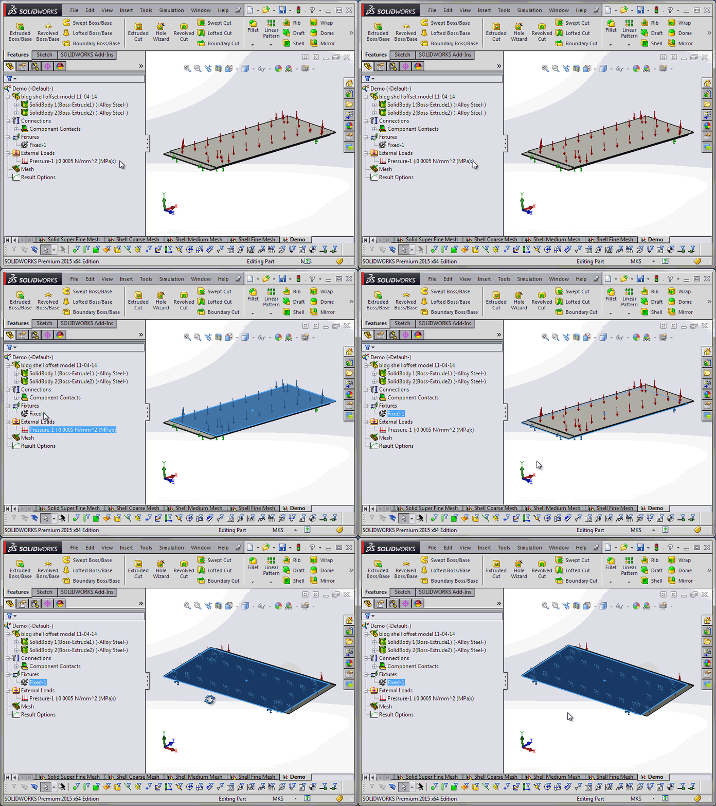
In SOLIDWORKS Simulation 2015, the process of previewing this and keeping shells consistent has some nice improvements. Let’s consider this example: we create a new study on a model with two thin stacked plates (both solid bodies) in Simulation 2015. There’s a pressure applied to one side of the stack and a fixture on the other.
We decide to use Define shell by selected faces to test how the shells will behave – defining the appropriate thickness first to avoid confusion.
Immediately, we see that the “top” face we clicked on (“top” in the sense that their outward normal points in the +Y global direction) corresponds to the default bottom side of the shell thanks to the orange preview coloring. But since the default offset defaults to midsurface, we want to change that. By setting the offset to top, we are telling the software that we want the face we’ve selected to be the top shell face.
Why might we want that? To be consistent with the global coordinate system and also the rest of the model, for instance. Furthermore, we want to define the shell on the same face the pressure load is acting on. We can then flip the default shell top/bottom alignment if needed using the “Flip shell top and bottom” option. In this case, this is necessary to have the shell thickness going in the proper direction – the preview makes this easy to visualize.
Whether we need to do this or not will depend on the aforementioned default top/bottom shell alignment. In previous versions of the software, we would need to wait until meshing to flip any shells that needed it, but starting in the 2015 version, we can define this from the very “birth” of the shell – and best of all, have that shell’s flip state persist even if we later choose to remesh. We then follow the same procedure for the bottom body, except this time we select the bottom face and offset since that is where the fixture is. No need to flip the alignment in this case.
Finally, one of the most important steps to verify the shell setup: mesh and render shell thickness in 3D. By doing this and comparing the positioning, alignment, and thickness of our shells, we can make sure the definition is correct.
Will this series of blog posts become a trilogy like so many movies do these days? Maybe… check back often so you don’t miss anything good!
Originally posted by Jay Seaglar in the SOLIDWORKS Tech Blog
![]() Find out more on SOLIDWORKS Simulation
Find out more on SOLIDWORKS Simulation
![]() Contact Sales
Contact Sales
![]() Request a Demo
Request a Demo


