Ever need to show more internal detail of an assembly in a drawing but needed it in an isometric view and sectioned as well? SolidWorks Drawings has this capability, and it’s easy and quick to achieve.
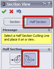
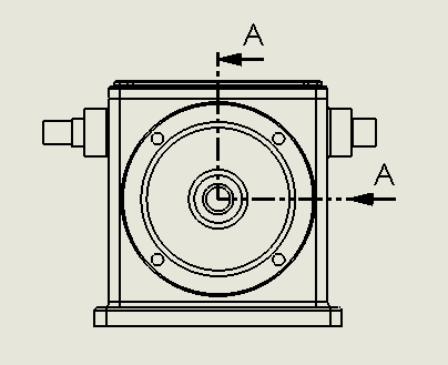
Start by creating an orthogonal view and then derive a section from it. It’s easy to get the section line where you want it by using the improved Section View command SolidWorks 2013. Select the Half Section option for the cutting line and position it appropriately.
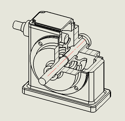
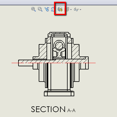
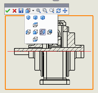
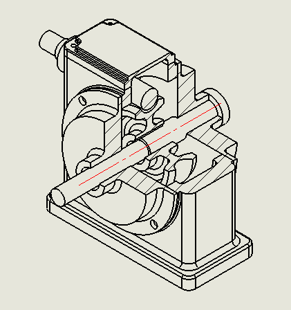
Once the section view is created, select it and rotate the view using the 3D Drawing View command on the Heads-Up toolbar; pick an isometric view or rotate it to any position you like. Once done, accept the changes.
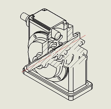
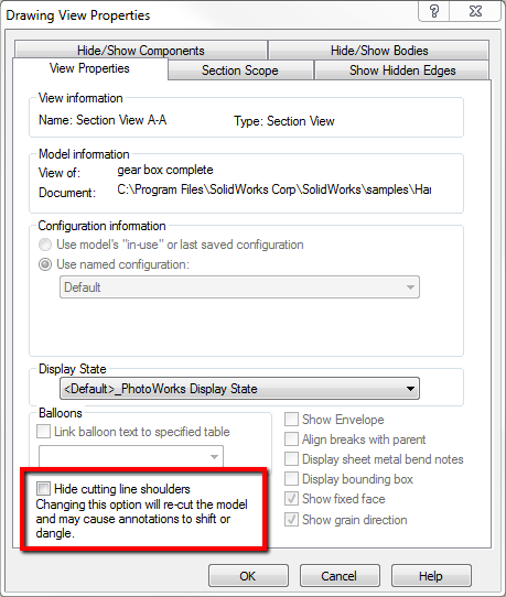
Since this is a true section view, and not an extruded cut in the assembly model, all the faces are hatched. You may notice that certain edges might be missing; this is due to the option that hides cutting line shoulders. Switch this option off from the Drawing View Properties (View Properties tab) and all the edges appear.
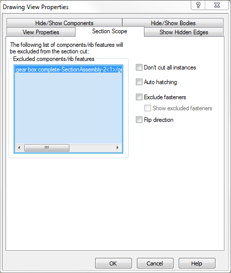
A final tweak to the 3D section view would be to select any components that don’t need to be sectioned. This can be easily achieved from the Drawing View Properties, in the Section Scope tab, and then selecting a component in the drawing view.
Hope you find this tip useful. More tips next time from the SolidApps team.